- Posts: 1083
- Thank you received: 187
ATA 28-41, Fuel Quantity
7 years 1 month ago - 7 years 1 month ago #540
by Mark
ATA 28-41, Fuel Quantity was created by Mark
The 767's (and from what I've seen, the 757 also) uses a somewhat different approach for obtaining fuel levels than most conventional fuel quantity measuring systems.
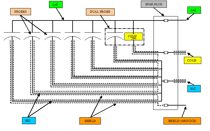
Aircraft such as the 727, older 737's, DC-9's, DC-10's, and A300 use a total of three wires (tank to processor/indicator) for tank measurement. The tank probes are combined at the tank spar plug and only LoZ, HiZ, and Comp wires are needed beyond the tank itself.
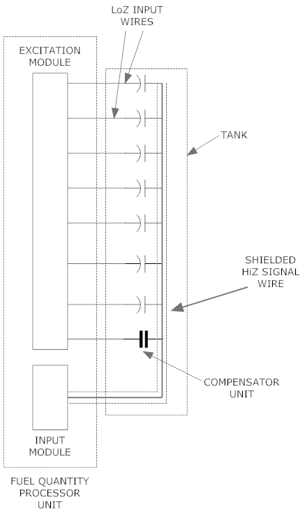
Each individual probe on a 767/757 has its own LoZ input excitation wire. The HiZ output wires are all connected together. This does include the compensator output signal.
The fuel quantity processor unit looks at each probe separately by using millisecond "shots" down each LoZ wire. Only one probe receives excitation at a time, so the output HiZ signal can be measured for just that probe alone.
If a probe is lost, the processor uses a "sister probe" method for estimating the missing probe's value.
The good thing about this approach is that faults can be isolated down to the exact probe vs using a breakout box for tank probe troubleshooting on the aircraft mentioned above. The bad thing though........ many more chances of wires breaking.
Last edit: 7 years 1 month ago by Mark.
Please Log in or Create an account to join the conversation.
- jake ounce
-

- Offline
- Premium Member
-

Less
More
- Posts: 133
- Thank you received: 0
7 years 1 month ago #541
by jake ounce
Replied by jake ounce on topic ATA 28-41, Fuel Quantity
That's why this site is so cool, because I would have never known this otherwise, thanks Mark!!
Please Log in or Create an account to join the conversation.
- jake ounce
-

- Offline
- Premium Member
-

Less
More
- Posts: 133
- Thank you received: 0
7 years 1 month ago #542
by jake ounce
Replied by jake ounce on topic ATA 28-41, Fuel Quantity
Does this system use a REF voltage for the LoZ side?
Please Log in or Create an account to join the conversation.
7 years 1 month ago #549
by Mark
Replied by Mark on topic ATA 28-41, Fuel Quantity
The LoZ excitation is usually a fixed A/C voltage. I've never actually read what it is, nor have I tried to measure it with a meter.
In older fuel quantity measuring systems, all probes received the same input reference voltage.
I'd have to assume it is the same for the 757/767 for all probes.
Because we're dealing with fuel...... whatever the voltage is, its small.
In older fuel quantity measuring systems, all probes received the same input reference voltage.
I'd have to assume it is the same for the 757/767 for all probes.
Because we're dealing with fuel...... whatever the voltage is, its small.
Please Log in or Create an account to join the conversation.
6 years 7 months ago - 6 years 7 months ago #590
by Mark
Replied by Mark on topic ATA 28-41, Fuel Quantity
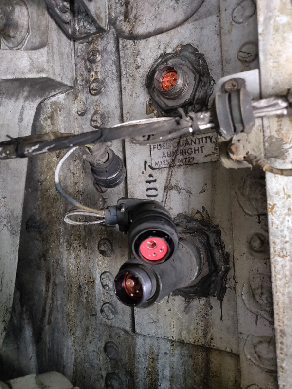
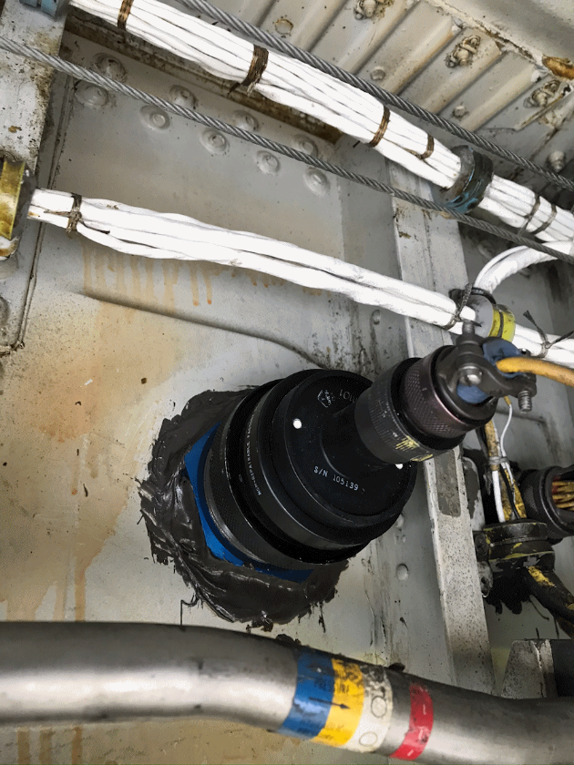
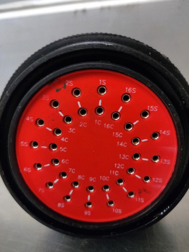
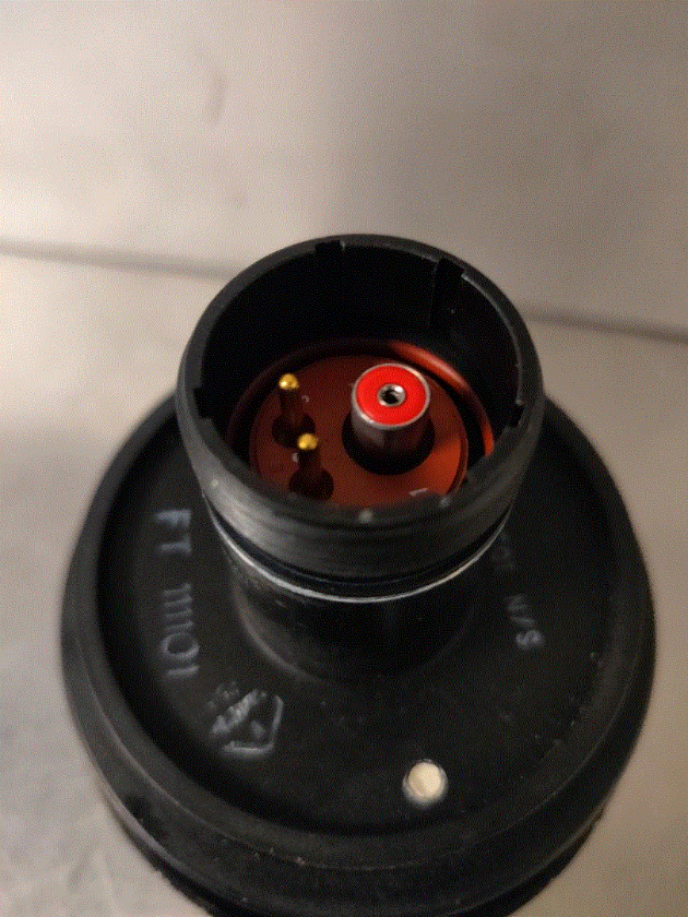
767 tank rear spar fuel quantity connectors and HiZ bussing plug.
The standard (from old 727, 737, and 747 days) three pin connectors are used. The LoZ and Comp pins are not used. The wider (shielded) HiZ pin is.
All LoZ and Comp wiring go through the upper plug.
As stated above..... more wires have advantages for usage (tank quantity reliability) and troubleshooting (isolation of single bad probe), but...... there is a whole bunch more crap that can break.
Last edit: 6 years 7 months ago by Mark.
Please Log in or Create an account to join the conversation.
5 years 9 months ago - 5 years 8 months ago #685
by Mark
Replied by Mark on topic ATA 28-41, Fuel Quantity
Found this in a 757 AMM
Tank Unit Signals and Programming:
(a) Strategically located tank units measure the fuel quantity in each fuel tank. Each fuel tank
also contains a compensator, which senses the dielectric of the fuel. Both the tank units
and the compensator are used in computing fuel quantity.
(b) With power applied to the FQPU, an excitation signal of 5 volts peak, 18.75 khz is sent to
the tank units to measure their capacitance value. This is accomplished by comparing the
tank unit against a rebalance capacitor of known value, which increments or deincrements
until a balance is reached. This operation is carried out for each tank unit, and
a computation of tank volume made by the microcomputer as follows.
1) The computer program divides each tank unit into 12 equal sections, and assigns a
value proportional to tank shape.
Wetted sections of the tank units are summed, and the value of unusable fuel
stored in the computer memory is subtracted from the total. Fuel quantity indicators
show the quantity of usable fuel.
2) The values assigned tank unit sections vary with airplane attitude. The computer
program contains four different characterizations for the ground conditions and four
for the air condition.
(c) The high frequency signal used for fuel measurement avoids interaction with other
airplane systems. The signal also tolerates low insulation resistance, and is not sensitive
to fuel contamination.
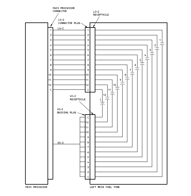
This is a better drawing than the one I have above.
Bussing plug for wing tank.
Location.
Last edit: 5 years 8 months ago by Mark.
Please Log in or Create an account to join the conversation.
5 years 9 months ago #686
by Clipper
Replied by Clipper on topic ATA 28-41, Fuel Quantity
It never dawned on me that the fuel measuring system would have 4 different air compensations depending on what I guess is would be for pitch angle.
Please Log in or Create an account to join the conversation.
5 years 9 months ago #688
by Mark
Replied by Mark on topic ATA 28-41, Fuel Quantity
The whole point of a capacitive fuel quantity system using vertical probes throughout the tank is that capacitance in parallel is "additive". If the aircraft is in a bank , the down-wing tank inner probes might have less fuel on them (less capacitance), but the outer probes will have more fuel (higher capacitance). The overall capacitance output remains the same. Thus, the quantity indication remains the same. The high wing would have less on the outer probes, but more on the inner probes..... the same rules apply.
Please Log in or Create an account to join the conversation.
5 years 9 months ago #689
by Clipper
Replied by Clipper on topic ATA 28-41, Fuel Quantity
Yes! That's why I was surprised to see it had multiple "characterizations"...I thought it was self compensating of different attitudes and bank angles due to the capacitor sensing. Do the A300s utilize a similar system for "tweaking" the quantity?And, I just reread your post, I missed that there were 4 ground characterizations...what is it adjusting for on the ground?
Talking about fuel, it brings back memories of planes that were taxied from the hangar to the terminal with very light fuel loads, and with just a little too much speed making the 90 degree turns to the gate, how the nose wheels would skid , horribly so with a damp ramp!
Talking about fuel, it brings back memories of planes that were taxied from the hangar to the terminal with very light fuel loads, and with just a little too much speed making the 90 degree turns to the gate, how the nose wheels would skid , horribly so with a damp ramp!
Please Log in or Create an account to join the conversation.
5 years 8 months ago #702
by Mark
Replied by Mark on topic ATA 28-41, Fuel Quantity
Please Log in or Create an account to join the conversation.
Time to create page: 0.834 seconds
Don't have an account?
Register now to join the community!
©
2026
Rotate.Aero
